RC Demon
The ultimate RC car
Early 2018
The goal is to explore the limit of RC cars.

Prologue
The former RC car was fast. However, it was hard to control due to its cheap tires’ low traction and ineffective suspension system. Furthermore, the FPV has a short-range, making it difficult to control at a long distance. Therefore, I have been thinking to design a completely upgraded RC car. Finally, at the end of grade 12, since the application season was finished, I started designing the new RC car which I named the RC demon. The goal is to design a larger car with open-wheel, a sealed body, a speed approaching 100kph, high grip, aerodynamic packages, and a long-range FPV system.
Design
Inspiration from F1
Suppose that you sit in a car. Before you use the throttle, you do not know in which direction the car will go because you cannot see the wheels. Although this may not be a problem in normal driving, it is undesirable in car racing because being able to predict the car path is important. In fact, I had a problem steering precisely when controlling the previous RC car and I had been looking for a solution. At last, I found the open-wheel design in Formula one cars a good solution.

Double layer car body
In order to see the wheels of the RC car while having a good view of the surroundings, the camera must be put at a higher position. Therefore, I decided that the car body must consist of two layers, one small layer at the top that has the FPV system, and one bigger layer at the bottom that is the main body of the car that has all the other components.

FPV
The former FPV system has a really short range. This is really undesirable because the new RC is designed to run at a much higher speed and requires a much bigger space. Therefore, I purchased a 1500mW high-power FPV this time. To help the driver to know the speed and the car status, I decided to install a microphone and some LED indicators that can be displayed on the FPV monitor.

Overall design objectives
The overall idea is like this.

Fiberglass and beam structure
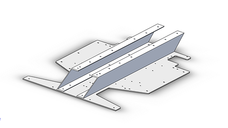
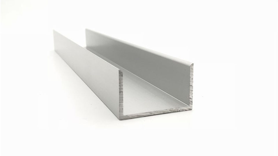
Through participating in the Robomaster Winter Camp, I found that the two-layer-plate base design is very simple and effective. As a result, I used the same strategy and design a two-layer-plate main body. C-channels are put in between the plates to increase the strength of the structure.

Tires
To improve traction, I purchased 4 105mm Slick tires this time. When I test them against the former RC tires, I found that they have a much higher grip.

Suspension
The former suspension is ineffective and to solve this problem, I decided to use the most classical suspension design – the MacPherson suspension. For my design, I have found that the shock absorber has to give double the normal force experienced by the wheel, which is approximately 40N when the car is in horizontal linear motion. Surprisingly, this happens exactly when the shock absorber that I bought previously is compressed 40% of its range, meaning that this design should just work fine.

Steering
If the steering bar is connected to the wheel hub directly, the mechanism will be much more complex. To simplify the steering system, I adopted the former design of connecting the wheel hub to a deck with a hinge, and the deck is connected to the car body with a hinge. The deck is then connected to the servo with a steering bar. The steering is trapezoidal to ensure efficiency.
.png)
Power and the motors
I chose the 5008 335kV motors because when connected to the wheel directly, it should give a speed of 25.2V*335RPM/V*0.105m*pi/(60s/min)*3.6kph/mps = 167kph on a 6s LiPo battery, which is in the range that I am aiming for. To prevent any transmission loss, I designed a coupler that fits the wheel on the motor to make it a hub motor.

Problem of tire expansion
Nevertheless, I found that the wheel spins too fast when using a 6s battery. The huge centripetal force causes the tires to deform a lot. In addition, adjusting the tires to obtain dynamic equilibrium is really hard. As a result, I decided to power the car with a 4s battery instead and it now should run at a speed of 16.8V*335RPM/V*0.105m*pi/(60s/min)*3.6kph/mps = 111kph theoretically.

Spoilers
The spoilers are for improving grip. Since the car runs at a high speed, the spoiler may experience a large force. If this force creates a moment, the servo will need to balance it and this may cause overloading. Therefore, I designed the parallelogram connection to be that when the spoiler is activated, the parallelogram is in its dead point. As a result, the servo is no longer under any load.

Prototype
The rest is putting everything together, manufacturing and building. After about one month of design and build work, I completed the prototype. The next is the adjustment stage.

Optimization

Electromagnetic interference
After testing, I found that I forgot to consider one very important thing – the electromagnetic interference created by the high-power FPV transmitter. The FPV is so powerful that it causes the 2.4GHz remote-control receiver to lose signal and the analog SG90 spoilers to deviate. Later I solved this problem by putting an aluminum channel under the FPV transmitter antenna which reflects the interfering wave.

Voltage drop
The FPV runs at 12V (3s) and is powered by the 4s battery using a step-down converter. However, I found that if the throttle is pushed too hard, the voltage of the battery drops below 12V and causes the FPV to shut off. This is a horrible problem since no one wants to lose control of the car at high speed. At last, I installed another 12V battery on the car that only powers the FPV to solve the problem. At this stage, the car was finally finished.

Showtime
The RC Demon
Car body
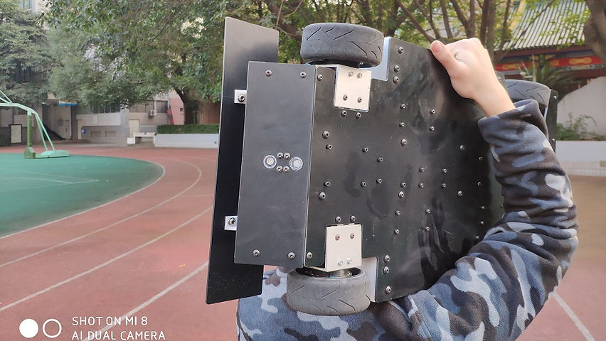
The RC Demon is an open-wheel design, slim body race car. The car body is a combination of fiberglass, aluminum, and ABS plate. It has excellent strength and even weight distribution.
 Overview |  Under maintainance |  CAD |
|---|---|---|
 Size comparision |  Top |  IMG_20181222_171244.jpg |
Power
The four 5008 335kV hub motors running on a 4s battery, the MacPherson independent suspension system, the powerful and efficient trapezoidal steering system powered by a 25kg MayTech servo, together delivers a high speed of 100kph and excellent controllability.
 Suspension |  Front tire |  CAD |
|---|
Spoilers
The side and back spoilers are activated automatically during braking and turning, or manually if high downforce is needed. They are powered by SG90 servos. At 100kph with the back spoiler activated, the car can generate downforce of 8N.
 Side spoiler, CAD |  Back spoiler, CAD |  Back spoiler |
|---|---|---|
 Side spoiler servo, inside the car body |  Back spoiler |  Side spoiler activated |
FPV
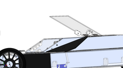
The ceiling plate is designed to be openable. One can read the voltage, turn on the power of the car, charge the car or turn on FPV. The three LEDs in front of the camera serves to indicate the status of the car on the monitor, left green shining means accelerating, middle green shining means high-power acceleration and right red shining means braking. There is also a microphone that records sound.
 Ceiling plate |  Inside the ceilling plate |  Camera, voltmeter, switches |
|---|---|---|
 FPV mode |  FPV indicators |  Acceleration light on |
Lighting system
To ensure safety when driving, the car has a front LED, a brake light and an acceleration light (blue color LED at the back).
 Front LED |  Brake light |  Overall |
|---|
Control and coding
Same as the last time, the servo and ESCs are connected to the 2.4GHz receiver directly and the program is preset. The left joystick on the remote control is the throttle and the right joystick on the remote-control controls steering. The rest of the car is controlled by an Arduino Uno. The code is a lot more complex than the last time because of the control of aerodynamic packages and the lighting system.


Here we go!
General explanation
What see the drifting again and hear the Doppler effect?

Retrospect
Interestingly, when I put the original design in Solidworks Flow Simulation and tested the downforce. I found that the downforce actually decreases from 3N to 1N when the back spoiler is activated. I thought this might be because the gap between the spoiler and the car body is a lot smaller, a low-pressure zone is created that pushes the car up. At last, I solved this problem by putting the spoiler at a higher position, and the car now generates an 8N downforce at 100kph. Anyway, I need to study more about fluid mechanics.
The car is a bit heavier than I thought, in total 9kg. This causes a little bit of overload to the motors if the throttle is pushed too fast. Reading from the spec sheet, I found that the 4-wheel-drive design, assuming a 70% motor efficiency, could produce a force of 4*9.55*0.7*271.2W/(0.6*24*335RPM)/(0.105/2m) = 28.6N and thus a 3.2m/s^2 acceleration for an 8kg car when each motor is running at 11.3A. This is a bit lower than expected and the optimal weight should be around 5kg. In addition, the motor is supposed to run on a 6s battery, but I could only let it run on a 4s battery because of the dynamic equilibrium and centripetal force problem. Next time when I design a high speed rotating mechanical system, I really need to consider dynamic equilibrium and centripetal force firstly and carefully.